
Case Study 2: Cavitation due to "High Air Ingression" into Pump Suction.
Problem Statement of Case Study 2
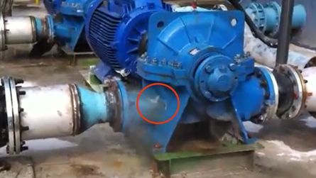
In an edible oil refinery, 2 units of cooling water circulation pumps were having some leaking issues. These pumps are BB-1 horizontal split-case pumps, where their sizes are 150-460 and were equipped with a 110 kW (4-pole) motors. However, a problem arose for these both pumps started when the water leaked or sprayed through the casing near to the pump outlet after running for less than two weeks.
At first, the customer suspected quality issue of the pumps as the problem occurred after the pumps operate for only less than 2 weeks. After investigation, the finding showed that the leaking of water was caused by the cavitation, which was due to “High Air-Ingression” into Pump Suction.
Keywords:
- Pump water leakage
- Cavitation
- Air-ingression
- Operating pump below minimum flow
- Pump start-up
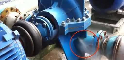
Pump No. 1 : Water Spraying at the Left Side of Casing.
Pump No. 2 : Water Spraying at the Right Side of Casing.
Findings of Problems
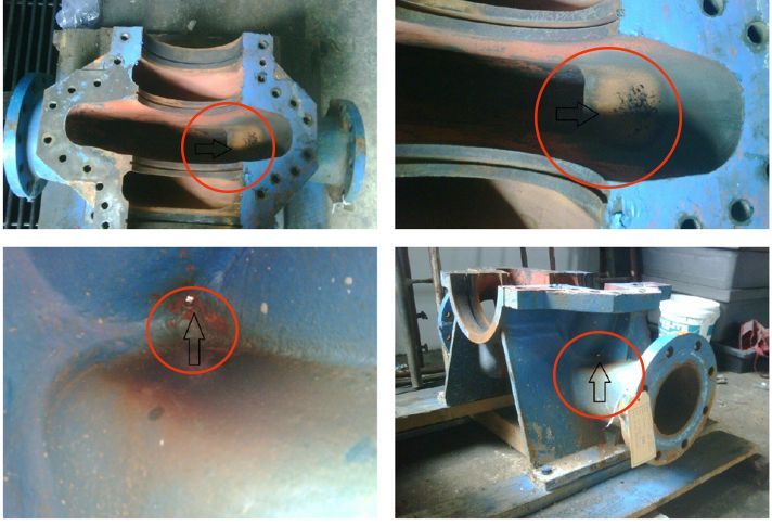
- Photos of Pumps Cannibalised for Close-Examination & Analysis
Pump No. 1 : Casing pitted and punctured with a Hole seen on the left side.
Pump No. 2 : Casing pitted and punctured with a Hole seen on the right side.
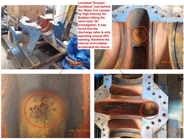
Initially, these photos seem like some kind of Chemical Attack on the Casing but when "knock" with a Screwdriver, it is still a very hard surface.
(If suffering from a chemical attack, the material will get softened and chip away.)
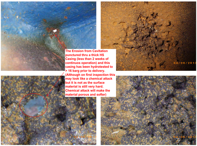
The illustration below shows signs of pitting by Cavitation on the pump (implosion of millions of tiny bubbles).
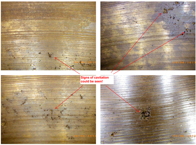
Microscopic Close-Up Photos on Cast Iron Casing.
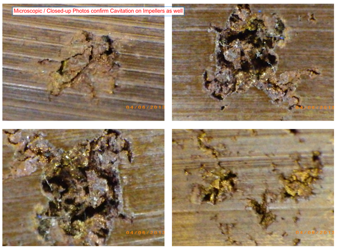
Microscopic Close-Up Photos on Bronze Impeller.
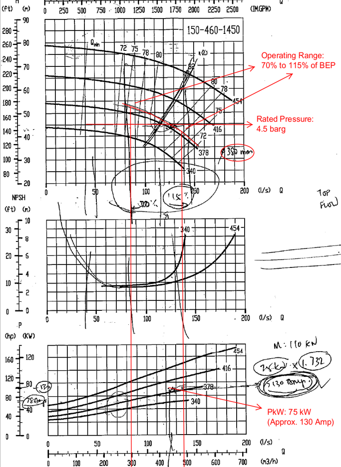
- Pump Performance Curve Analysis
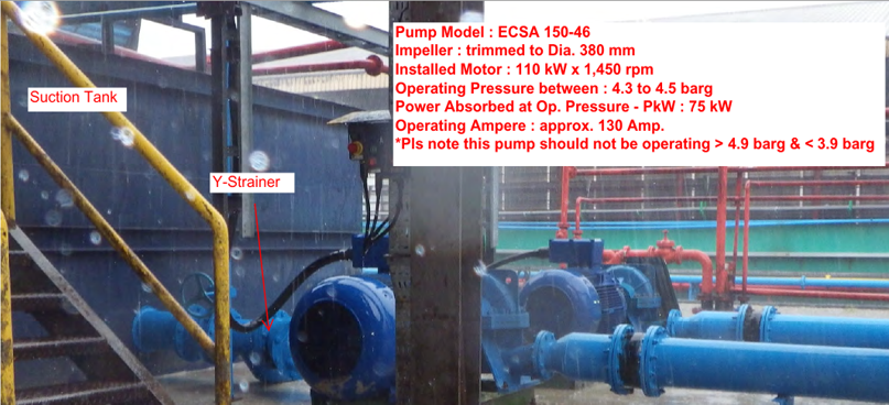
The pump in question has a size of 150-460, an outlet of DN 150 mm, and an impeller diameter of 380 mm (trimmed). Its rated flow is 450 m3/h, with a rated head of 4.5 bar (g). The expected operating amp at rated flow is around 130 amps, equivalent to 75 kW. However, during measurement, the pump was running at 78 amps, or 45 kW, resulting in a flow of only 70-75 m3/h, which is less than 20% of the rated flow. This indicates that the pump was not operating within its "healthy" range. Unfortunately, during the site visit, the pressure gauge was not operational, so the pressure could not be directly measured. However, the flow was determined from the operational amp readings, allowing for adjustments to ensure the pump operates within the recommended parameters.
Upon investigation, it was determined that the premature failure of the pump was caused by cavitation, triggered by air-ingression from the suction tank. This was attributed to the cooling water return line from the plant being too close to the pump intake line. To rectify the situation, the client has relocated the return pipe line away from the pump intake line.
- Advice Given:
Please do not operate the pump below the minimum flow. Instead, the recommendation is to operate at the rated head/pressure of 4.5 bar (g).
Pump Performance curve of cavitated pumps
Some Important Points to Note for "Trouble-Free Pumping"
Some factors that may leads to "Air-Ingression" into the pump:
- To prevent the water returning to the suction tank from carrying excessive air bubbles, it's essential to implement a solution. One effective measure is to avoid directing the return water straight into the pump suction pipe. Instead, consider redirecting the flow or incorporating a buffer plate to divert the water. This design modification aims to eliminate any potential vortex formation or the entrainment of air bubbles in the process. Another beneficial addition is the incorporation of a vortex-breaker on the suction pipe. This device helps disrupt any swirling motion in the fluid, minimizing the likelihood of air being drawn into the pump during operation.
- Suction Line - Ensure the Y-strainer is cleared and flanges are all properly tighten to eliminate " Air-Ingression" .
- Proper Pump Start-up is important. Before operating the pump, priming operation has to be performed in the following steps:
- Open the priming valve or bleeder plug at the top of the pump.
- Next, open the discharge valve to about 50 %.
- Then open the suction valve " SLOWLY" and prevent the water from sudden rush-in.
- Close priming valve when water flows out
- Check Discharge Pressure Gauge that it should show the static suction head (Example: Water level = 2.0 m ; Gauge should register 0.2 barg or 0.2 kg/cm2)
- Then close the discharge valve and PREPARE to start the electrical motor.
- Read the Gauge and it should show the Max.Shut-off Head (Example: 54 m or 5.4 barg) at rated impeller diameter of 380 mm.
- Open Discharge Valve slowly until 4.3-4.5 barg.
- If pump is running noisy, stop the pump immediately and repeat the steps all over again.